|
PCTRAN: A PC-based Simulator
For the Westinghouse AP1000
At the start of 2007, more than twenty units of
Westinghouse's AP1000 are either committed or on the verge of contract placement.
The new generation of passive safe plant has accelerated construction schedule
as short as six years. Therefore, preparation of a training program on the
advanced technology is imminent for utility companies. Micro-Simulation
Technology has over twenty-years experience in development of nuclear plant
simulation software. Over ten years ago we developed a PC-based simulator
for AP600. In order to meet current demand, it is up-scaled to AP1000 and
revised for the Microsoft Windows XP environment. Download the free demo.
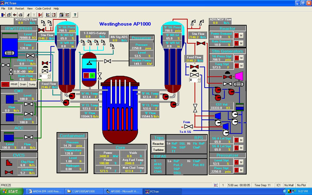
For AP1000's nuclear and secondary steam supply system,
despite numerous evolutionary improvements, it is similar to the conventional
PWRs. The reactor primary coolant has two steam generators with four coolant
pumps (2x4 configuration). PCTRAN's right hand side control panels are similar
to a conventional PWR. At left there are panels for the passive emergency core
cooling systems (PXS). At top there is the In-Containment Refueling Water
Storage Tank (IRWST). The passive residual heat removal (PRHR) heat exchangers
are submerged in the IRWST. Three stages of automated depressurization system
(ADS) on top of the pressurizer are provided to relieve steam into the IRWST
during a small break loss-of-coolant accident. The fourth stage ADS valves are
connected to the hot legs and relieve steam directly into the containment
atmosphere.
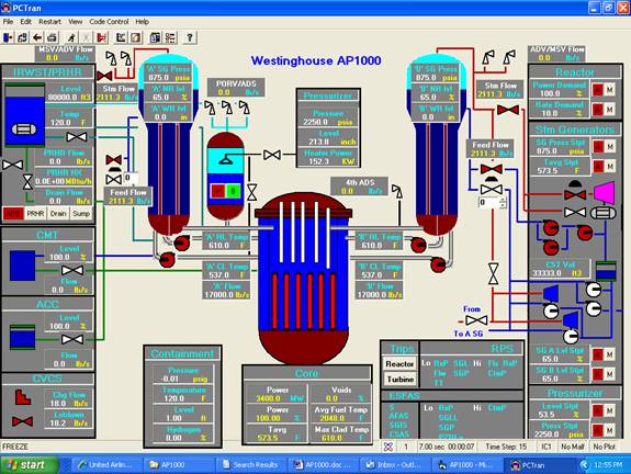
Instead of an active high-pressure injection system, that
requires safety-graded pumps and emergency AC power supply, the passive systems
of coolant makeup tanks (CMT), accumulators (ACC) and IRWST drain valves are
modeled. For containment cooling, the RB spray and vent valves are provided.
Different from the conventional spray inside the containment, the spray is
applied on the outside shell of the steel lining. Film cooling promotes
natural air draft from ambient atmosphere to vent through top of the
containment. The valve color changes and digitally displayed flow rates
indicate activation of the passive systems. Operators usually do not have to
interfere with the valve status other than verify and observe its evolution.
AP1000 has inherently safe characteristics. The reactivity
coefficient is negative at all times; that halts the chain reaction in the event
of any expected power increase. The core is rated at 3400 MW thermal at full
power. The hot and cold leg temperatures are 310:C (610:F) and 280.5:C (537:F)
respectively. These are faithfully reproduced for steady state by PCTRAN in
its NSSS mimic.
Inventory Control for the Reactor Coolant System
If the reactor makeup system is unavailable, CMT provides
passive reactor makeup. The tanks are designed for full RCS pressure and are
located above the RCS cold loop piping. It is activated on a low pressurizer
water level or low RC pressure safety injection signal. In either case, the
reactor is scrammed, the RCP's are tripped, and the CMT's isolation
air-operated valves automatically opened. If a large LOCA occurs, the
accumulators are needed to provide a high makeup flow rate. Borate water under
nitrogen pressure of 48.3 bars ensures filling of the reactor vessel lower
plenum and down comer following a RCS blow down. After the RCS is completely
depressurized, IRWST isolation valve is opened to provide water into the RCS by
gravity draining.
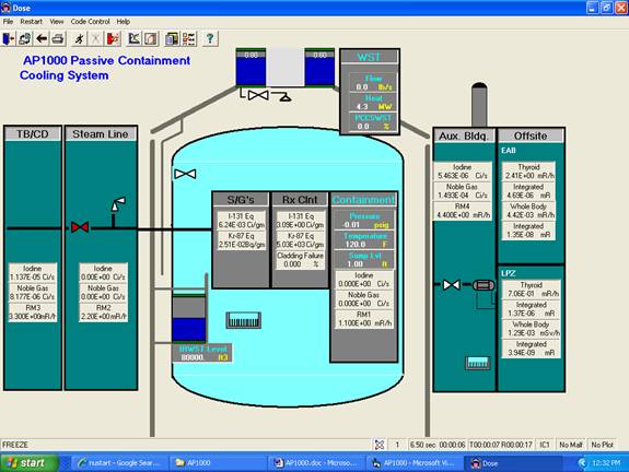
The Passive Containment Cooling System (PCCS)
The atmosphere is the ultimate heat sink for the reactor
system. For a design basis scenario, core decay heat is transferred through
the containment vessel to the environment. The containment concrete structure
with the baffle provides for natural circulation of outside air. The air
enters into the gap between the concrete containment and the baffle at the top,
flows down the outside of the baffle, and rises up along the steel containment
vessel. The heat transfer is enhanced by a water film formed by the gravity
drain of water onto the containment shell from the PCCS water storage tank,
that is located at the top of the concrete structure. The tank has sufficient
water to provide three days of cooling. The PCCS system is activated in the
event of high-pressure reading within the containment. Such an event would
take place if the normal heat removal (the containment fan coolers) were
unavailable for an extended period of time. Download the free demo.
Trip Set Points
- "S" signal of low pressurizer pressure = 127 bar for reactor trip, steam generator
feedwater control valves close, PRHRS isolation valves to open and CMT
isolation valves to open
- MSIVs close 10 seconds later
- Accumulators start to inject water to RCS when the primary pressure decreases to 48.3 bar
- First Stage ADS valves open at CMT level decreases to 67%
- Second Stage ADS valves open at 70 seconds later
- Third Stage ADV valves open at 120 seconds later
- Fourth Stage ADS valves open at CMT level decreases to 20%
- Passive IRHR isolation valves automatically opened at 0.83 bar (12 psig)
|