 Home | Contact us
The August 23 earthquake at the North Anna Nuclear Plant site of Mineral, Virginia in USA was measured Scale 5.8. It is “uncomfortably close” to its designed limit of 6.2. There are 2 units of Westinghouse 3-loop PWR of 900 MW electric output. Four diesel generators started as expected after the grid loss and reactor shutdown. But one failed shortly after and the remaining three were able to provide heat removal. The grid was also recovered afterwards so that no damage has occurred at North Anna. Should more diesels fail or the grid power not resumed for extended period, our analysis shows the consequence could be serious.
North Anna is basically the same as the Spanish Vandellos II and Taiwanese Maanshan (Horse Saddle Mountain) plants. MST has delivered its PCTRAN plant specific models to both since early 90’s and thus is familiar with their transient and accident behavior.
For an earthquake-induced loss of offsite power (LOOP) event the FSAR has analyzed both with and without onsite diesel generator events. Without onsite AC to power it is call station blackout (SBO). Lack of core, containment and spent fuel pool cooling the plant will enter into a severe accident. Following is our study of the plant condition in later stage with failed core and dose release.
Station blackout core meltdown and vessel failure condition.
Without AC the following systems are inoperable:
The diesel generators fail to start so the following systems are inoperable:
In the event of the DC-powered control of the turbine-driven auxiliary feedwater pump fails or the condensate storage tank inventory is exhausted, feedwater to the SG’s will stop. Then the only heat sink of the core decay heat is from the SG’s atmospheric dump valves. Its inventory will boil dry in about one hour.
Following are transient plots generated by PCTRAN. We should note that the primary will be heated up to saturation and over-pressurized to lift both the pressurizer relief valves and safety valves. Fluid discharge into the reactor coolant drain tank will pressurize it soon and break the rupture disk (similar to TMI-2 event). Continued discharge of RC coolant pressurizes the containment since neither of the containment spray and fan coolers are available.
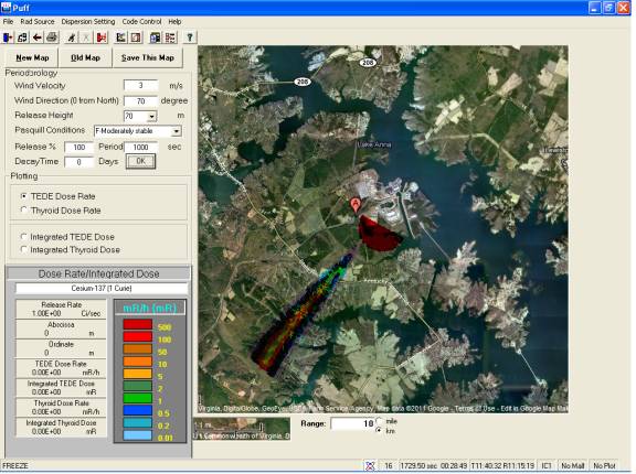
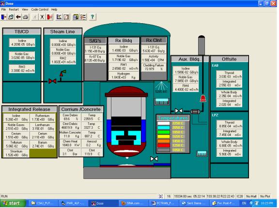
In a matter of hours the RCS loss of coolant exposes its core and the fuel assemblies heat up to melting. When significant amount of core melt it may collapse and fall to the bottom of the core. Continued heating of the vessel bottom it would melt through the vessel bottom. The hot debris would interact with the cavity floor concrete and generate aerosols. At a high containment pressure far exceeding its design of about 4 atmospheres the containment boundary may breach. Radiological release (source term) into the environment will disperse according to the wind plume direction.
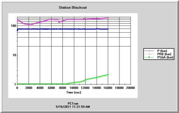
P = RCS pressure, PRB = Reactor Bldg pressure, PSG = SG pressure
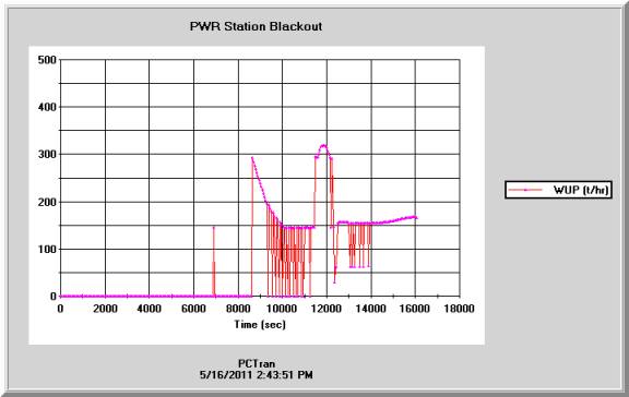
WUP = Pressurizer top fluid discharge rate
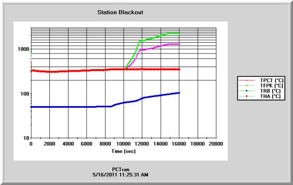
TPCT = Peak clad temp, TFPK = peak fuel temp, TRB = RX Bldg Temp, THA – RC hot leg temp.
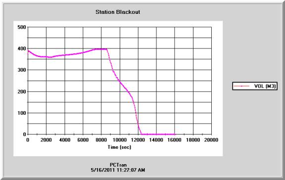
VOL = RC liquid inventory
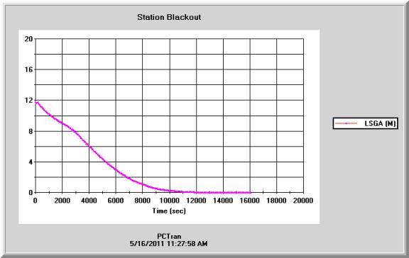
SG secondary water level
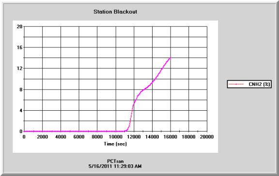
Containment hydrogen concentration
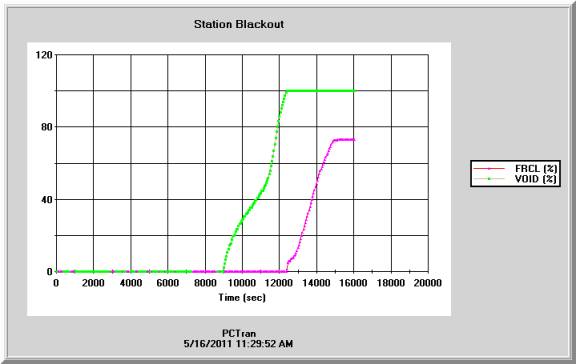
VOID = RCS void percentage, FRCL = fraction of clad failure
In the course of the transient, the SG atmospheric relief valves cycle around their opening set point at about 74 kg/cm2 until completely dry. The RCS primary is heated up to saturation. The pressurizer relief valves also cycle around their set points. When the pressurizer level reaches its top, the discharge turns into liquid. It continues until a significant amount is discharged so it turns into two-phase and back to vapor. Continued loss of primary coolant exposes the core. So the fuel temperature heats up to its melting temperature about 2250ºC, the melting temperature. The core then melts and drops to the bottom of the vessel. Eventually it will melt through the vessel bottom into the reactor cavity.
The containment high concentration of radiological isotopes will leak through the containment boundary at high pressure. Using our RadPuff dose projection software to process the source term under a meteorological condition of northeast wind, the following plume diagram is resulted.