 Home | Contact us
2008 International Congress on Advances in Nuclear Power Plants (ICAPP '08)
Embedded International Topical Meeting at the 2008 ANS Annual Meeting
June 8-12, 2008 • Anaheim, California, USA
Li-chi Cliff Po
Micro-Simulation Technology
10 Navajo Court
Montville, New Jersey 07045
1-973-263-7327
[email protected]
Abstract – The PC-based reactor simulation software PCTRAN was expanded to cover light water advanced nuclear power plants. The plant models include Generation III+ advanced PWR and BWR. The evolutionary ones are Areva, Mitsubishi and Korean Advanced PWR’s and GE ABWR. Adding cooling path redundancy and devises for severe accident mitigation has enhances reliability. One-step further is the passive-cooled Westinghouse AP1000 and GE ESBWR. PCTRAN’s ESBWR and AP1000 models are introduced in this paper. The PC-based simulator will help training and evaluation on the advanced technology for countries and utility companies entering into the second coming of nuclear era.
PCTRAN is a code using reduced thermal hydraulic nodes for transient prediction. A moving boundary condition between the saturated two-phase and subcooled regions allows the number of nodes significantly reduced to simplify numerical solution. Since its first introduction1 in 1985, it has evolved from DOS to Windows-XP environment. Operation is in standard graphical-user-interface (GUI) for friendly interactive control.
For AREVA EPR, there are four trains of the independent emergency core cooling system and double containment. The large components such as the pressure vessel and its internals, the steam generators and the primary coolant pumps assure modest response during disturbance from normal operation. Should they still fail and a core-melt takes place, the molten core material would be collected and cooled in the cavity area. PCTRAN’s six-node core model for severe accident has successfully reproduced this scenario.
Westinghouse AP1000 uses passive heat sink and natural forces to remove decay heat. There are inside-containment refueling water storage tank, accumulators, coolant makeup tanks, passive residue heat removal system and automated depressurization system. For any disturbance it relies on natural course to depressurize the primary coolant and let coolant cover the core effortlessly. The containment is cooled from outside its steel liner by water draining from a tank above the roof. Air draft from the ambient further assists this process. PCTRAN AP1000 rigorously demonstrates all these in vivid animation. It is of high fidelity as the simulated results have been benchmarked against the approved Final Safety Evaluation Report.
The General Electric ESBWR relies on the use of natural circulation and passive safety features to enhance the plant performance and simplify the design. It was based on the earlier Simplified BWR (SBWR) by economics of scale to a higher power level of 4500 MWt (1560 Mwe). The use of recirculation pumps in previous BWR models or reactor internal pumps for ABWR is completely eliminated. Core flow is by natural circulation. Natural circulation is further used for emergency core cooling and containment cooling. In the event of steam line leak or break, the reactor is shutdown by inserting all control rods from the bottom. The feedwater continues to maintain the water level in the vessel.
In the US most utilities planning for advanced reactors have already selected their plant types. The new plant type is significantly different from its current staff’s experience. Despite a replica simulator is in order, when completed it could only suffice control room operator’s training. For vast technical and managerial personnel, PCTRAN could be used for general training to familiarize them with the advanced system’s dynamic performance. It supplements vendor’s supplied text and drawings.
In the international market, a number of countries are adopting nuclear power for the first time. Other than relative economical terms, PCTRAN could be used for technical evaluation between plant designs. It is also a training tool for first generation personnel to show basic concepts such as criticality, control systems, emergency cooling and accident mitigation.
In this paper two of the above advanced plant types – ESBWR and AP1000 - were selected for simulator presentation. Their designs of user-graphic-interface (GUI) and verification analyses against published safety evaluation reports are described.
GE/Hitachi’s ESBWR Design Document2 was used to model PCTRAN/ESBWR main mimic. The nuclear steam supply system (NSSS) is designed in a mimic as shown in Fig. 1a. The use of recirculation pumps in previous BWR models or reactor internal pumps for ABWR is completely eliminated. Core flow is by natural circulation. The core flow/power map is a single curve (Fig. 1b). Natural circulation is further used for emergency core cooling and containment cooling. In the event of steam line leak or break, the reactor is shutdown by inserting all control rods from the bottom. The feedwater continues to maintain the water level in the vessel.
In the event of AC power is lost, the ESBWR utilizes the Isolation Condenser System for high-pressure inventory control and decay heat removal. In PCTRAN/ESBWR main mimic it is located in the upper right of the reactor vessel. The isolation condenser system has four independent loops. By clicking the scroll bar users can activate one to four trains. The steam is driven by natural circulation upward to the condenser tubes; where it is condensed by the pool water and drain back into the vessel.
If the water level continues to fall for a larger break, the Automatic Depressurization System (ADS) is activated to allow low-pressure inventory control. It consists of 10 safety relief valves (SRVs) and 8 depressurization valves (DPVs) connected to the steam line. The SRVs discharge steam to the suppression pool and the DPVs discharge to the drywell respectively. A timely sequence of opening of these valves allows the water from the Gravity Driven Cooling System (GDCS) tanks to flow into the vessel by gravity. The Standby Liquid Control system (SLC) is also activated. It uses nitrogen-filled tanks to drive borated water for coolant makeup.
Containment cooling is provided by the Passive Containment Cooling System (PCCS) in the mimic’s upper left side. The system contains four loops; each has a heat exchanger open to the containment, a condensate drain line and a vent discharge line submerged in the suppression pool. The PCCS limits containment pressure to 40 psig (about 4 atmosphere). The passive systems have been successfully analyzed to maintain the fuel covered at all time (without heat-up) and the containment stay cooled for three days. PCTRAN/ESBWR has duplicated all these scenarios consistent to GE’s document.
The Windows version is a state-of-the-art product taking full advantage of 32-bit PC technology. The source code is completely re-written using Microsoft Visual Basic 6. Operation follows strictly the Microsoft Windows XP environment. Data input/output are in Access database format. Reports and data can be transferred conveniently through Office Suite over a network. Execution is default to real-time speed. It could be accelerated to 2, 4, and 8 or up to16 times faster. Selection of equipment malfunctions and accident types are from a drop-down menu. It includes all possible disturbances to a plant:
Online “Help” is provided that assists comprehensive user’s manual for easy instruction.
A turbine trip with bypass transient (TTWB) and a main steam line break (MSLB) inside containment bounding case were analyzed using PCTRAN/ESBWR for benchmark against the Design Document2. For TTWB, the Alternate Rod Insertion (ARI) is initiated that reduces the reactor power to about 60% with feedwater and steam bypass flow runback to about 40%. Loss of feedwater heating (and thus a greater enthalpy difference to that of steam) is the cause for more reduction in feed and steam flows than the power. The reactor dome pressure, drywell and suppression pool pressures and temperatures are compared in the following figures. They are generally in good agreement.
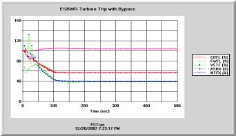
Fig. 2a ESBWR Turbine Trip with Bypass, Heat flux and neutron flux, feedwater, steam and core flows: GE Document (left) vs.PCTRAN (right)
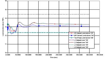
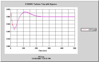
Fig. 2b ESBWR Turbine Trip with Bypass, Vessel downcomer water level in cm above TAF, Left (GE Document) vs. PCTRAN (right)
Next a double-ended 950 cm2 steam line break is initiated inside the dry well. The reactor is depressurized while blowdown of the steam inters the suppression pool. Heat-up in the drywell air then enters into the PCCS pool by natural circulation that limits the containment pressure to about 2.4 atmospheres. The PCTRAN/ESBWR results are in good agreement with the Design Document.
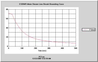
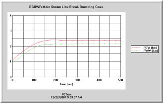
Fig. 2c ESBWR MSLB - Reactor dome pressure, DW and WW pressures and temperatures
Top one (GE Document) vs. PCTRAN (Bottom 2)
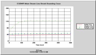
Fig. 2d ESBWR MSLB DW and WW temperatures: left (GE Document) vs. left (PCTRAN).
Westinghouse4 AP1000’s NSSS is similar to conventional PWRs. The reactor primary coolant has two steam generators with four coolant pumps (2x4 configuration). PCTRAN’s mimic (Fig. 3a) right hand side panels are for normal operation control. At left there are panels for the passive emergency core cooling systems (PXS). At top there is the In-Containment Refueling Water Storage Tank (IRWST). The passive residual heat removal (PRHR) heat exchangers are submerged in the IRWST. Three stages of automated depressurization system (ADS) on top of the pressurizer are provided to relieve steam into the IRWST during a small break loss-of-coolant accident. The fourth stage ADS valves are connected to the hot legs and relieve steam directly into the containment atmosphere.
Instead of an active high-pressure injection system, that requires safety-graded pumps and emergency AC power supply, the passive systems of coolant makeup tanks (CMT), accumulators (ACC) and IRWST drain valves are modeled.
AP1000 has inherently safe characteristics. The reactivity coefficient is negative at all times; that halts the chain reaction in the event of any expected power increase. The core is rated at 3400 MW thermal at full power. The hot and cold leg temperatures are 310ºC (610ºF) and 280.5ºC (537ºF) respectively. These are faithfully reproduced for steady state by PCTRAN in its NSSS mimic.
If the reactor makeup system is unavailable, CMT provides passive reactor makeup. The tanks are designed for full RCS pressure and are located above the RCS cold loop piping. It is activated on a low pressurizer water level or low RC pressure safety injection signal. In either case, the reactor is scrammed, the RCP’s are tripped, and the CMT's isolation air-operated valves automatically opened. If a large LOCA occurs, the accumulators are needed to provide a high makeup flow rate. Borate water under nitrogen pressure of 48.3 bars ensures filling of the reactor vessel lower plenum and down comer following a RCS blow down. After the RCS is completely depressurized, IRWST isolation valve is opened to provide water into the RCS by gravity draining.
III-B The Passive Containment Cooling System (PCCS)Westinghouse has submitted a Final Safety Evaluation Report (FSER) and USNRC approved it in 2005. For a complete spectrum of loss-of-coolant-accidents (LOCA), the core is never uncovered. PCTRAN has basically reproduced these results with comparable pressure, temperature and water inventory transients. The CMT, accumulator, and ADS systems work well to depressurize the RCS and provide coolant makeup. The PRHR heat exchanger removes the decay heat. The passive containment system supplies coolant from the highly located WST that enhances natural air draft cooling by the atmosphere. These phenomena are quantitatively demonstrated with vivid graphics and animation. It is therefore an indispensable tool to supplement text material for a comprehensive AP1000 training program.
The case of inadvertent ADS initiation by opening one of the first stage valves was analyzed. The reactor is then tripped on low pressure and the “S” signal tripped the reactor and coolant pumps, started the CMT and accumulator injections. Following are pressure comparison.
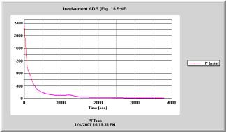
Fig. 3c AP-1000 ADS Initiation – Reactor Pressure -Left (FSER) vs. Right (PCTRAN)
A 10-inch (500 cm2) cold leg break is initiated. After the reactor trip on low pressure and containment high pressure “S” signal, the coolant pumps trip, steam generator isolation, start of the CMT, PRHR, accumulators and ADS occur subsequently. PCTRAN’s results are shown in the following figures. The break discharge soon turns from liquid to two-phase as the cold leg is exposed. It is witnessed by the break specific enthalpy. Comparison with FSER Case 15.5.5.4B- shows basic agreement. There is no core exposure and heatup.
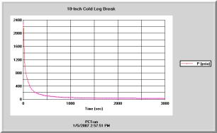
Fig. 3d AP1000 10-Inch Cold Leg Break Reactor Pressure – left (PCTRAN) vs.right (FSER)
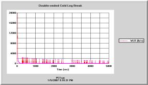
Fig. 3e AP1000 10-Inch Cold Leg Break Flow – left (FSER) vs. right (PCTRAN)
A 3000-cm2 hot leg break is initiated without any operator actions. The reactor building pressure calculated by PCTRAN and FSER are compared in Fig. 3f.
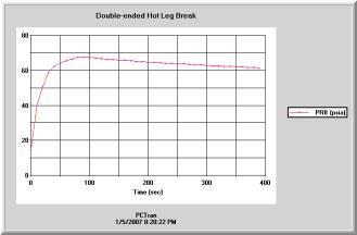
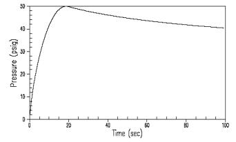
Fig. 3f AP1000 FSER DEHL LOCA.RB pressure
The PC-based code has successfully moved into advanced light water designs. Inherent safe and passive cooled systems were demonstrated for ESBWR and AP1000. Benchmark against published document shows general agreement. For countries or companies going into nuclear power for the first time, it provides a training tool supplementing classroom lecture by dynamic demonstration. Students also get hand-on experience in both normal and accident response. Furthermore, the family of codes can be used for evaluation between various designs in their response to multiple failures and human error. Prior to actual construction of a plant or its full-scope training simulator, it serves as a valuable tool
heading to the second coming of the nuclear era.
References
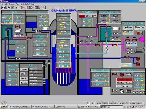
Fig.1a PCTRAN/ESBWR Windows Mimic
Fig. 1b ESBWR Stability in Expanded Operating Map
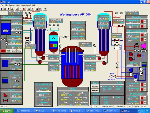
Fig. 3a PCTRAN Westinghouse AP1000 NSSS Mimic
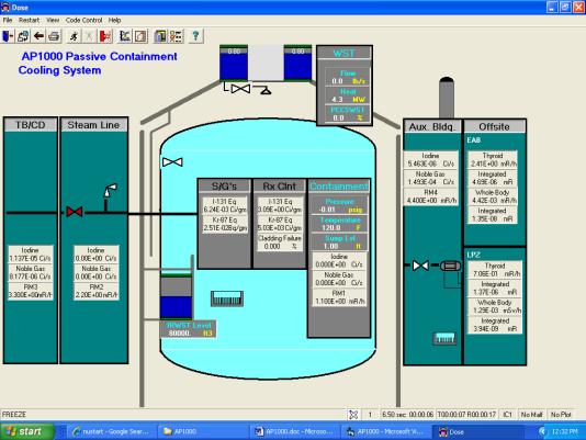
Fig. 3b PCTRAN/ AP1000 Passive Cooling Containment Mimic