 Home | Contact us
Micro-Simulation Technology
September 2014
The EPR includes a number of additional features to prevent or mitigate the effects of severe accidents:
The IRWST and Severe Accident Depressurization valves are described in the Safety Injection and Pressurizer in the existing version of PCTRAN/EPR. Recent work has expanded the following systems:
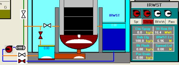
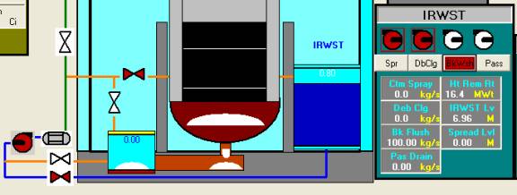
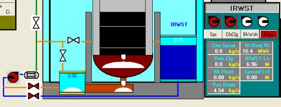
1. Severe Accident Heat Removal System
The PCTRAN/EPR user interface is shown in the following mimic. As can be seen, the Combustible Gas Control System is at the lower-left corner. The instrument and controls of SARHS and IRWST are at both sides by the reactor vessels. The core debris catcher and spread area are below the vessel. The Annulus Ventilation System panel is right to the reactor building.

The radiation monitors’ readings and release source terms of noble gases, iodine and molten-fuel heavy isotopes are displayed in each compartment.
The dedicated ex-vessel system is to accommodate molten core debris in the event of vessel breach. It has four modes of operation:
The containment building and shield building are separated by an annular space that is maintained at sub-atmospheric pressure by the Annulus Ventilation System (AVS). The AVS is a safety-related system used to filter any leakage through the primary containment, in the event of both design basis and severe accidents, prior to releasing it from the plant stack. The AVS ensures 2x100% extraction capability and consists of a high efficiency particulate air (HEPA) filters and charcoal absorbers in series with air handling equipment.
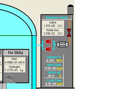
When the system fans are turn on, the containment pressure and radioactivity will be reduced. The highly radioactive iodine will be vented through the HEPA filters that are rated to 99% efficiency. Nevertheless, a tradeoff of elevated noble gases or whole-body dose will be released into the atmosphere without any filtration effect. Therefore decision of activating this system should be prudent as a very last resort.
It consists of 41 large and 6 small passive autocatalytic recombiners (PARs) in the containment. In the lower left corner the panel is:
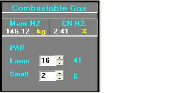
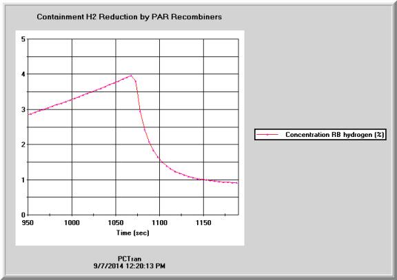
When hydrogen concentration in the containment is elevated to elevated level, operators may active a number of the PAR recombiners to reduce its concentration. In the transient figure below the concentration was increasing following a large break LOCA without ECCS with significant core damage and hydrogen in the containment. The operator turns on a number of recombiners, the concentration drops rapidly.
PCTRAN as has all above systems and their respective functions modeled for dynamic simulation. As a result, students learn severe accidents in realistic and vivid hand-on exercise of the mitigation process.
The original EPR illustrations of these systems are shown below for reference.
. 

The radiation monitors’ readings and release source terms of noble gases, iodine and heavy isotopes are displayed in each compartment. The data is saved and transportable to the software RadPuff for area dose projection.