 Home | Contact us
PCTRAN SMART Small Modular Reactor Simulator
Micro-Simulation Technology
SMART is a 330 MWt pressurized water reactor with integral steam generators and advanced safety features. The unit designed by Korea Atomic Energy Research Institute (KAERI) for electricity generation (up to 110 MWe) as well as thermal applications such as seawater desalination.
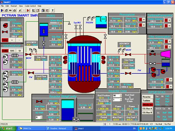
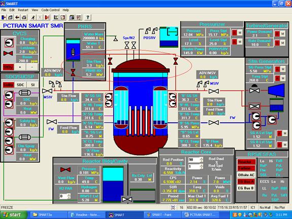
Shown below in PCTRAN/SMART graphic user interface, the center reactor vessel contains the pressurizer at the top. Eight helical coil once-through steam generators are lumped into two and 4 canned motor pumps are modeled inside the vessel. In the upper left chemical and volume control (CVSS) system panel, the charging pump and letdown valve control the pressurizer level and coolant chemistry. Boron concentration can be raised or lowered simply by clicking on the + or – buttons respectively. The level, pressure, their respective set points and safety relief valve flow rate are displayed near the pressurizer. Below CVCC is the shutdown cooling (SDC), safety injection (SI) and containment spray (CS) control panels.
In the upper right corner there is turbine/generator control panel. Turbine power can be varied by setting the demand and change rate, the reactor and entire plant control will follow as designed. Right underneath is the steam generator control of its header pressure. Feedwater flow is adjusted to match the desired SG level. Further down is the reactor protection system (RPS) with the reactor scram and, trip and AC power buttons. The actuated trips are indicated in red. The emergency feature actuation system (ESFAS) that start the SI and CS trips are also indicated by red flags.
Middle lower right is the reactor core control. Rod assemblies in their total withdrawn percentage can be changed to adjust the core power. In this mode the turbine follows the reactor. The neutron flux, reactivity, core fuel temperature and void fraction are displayed. To its left is the containment panel to show its thermal-hydraulic conditions. The in-containment refueling water storage tank (IRWST) provides water for SI and CS pumps. It also collect water spill from a loss of coolant accident. There is mechanism to shift water into the reactor cavity in the event of core-melt treat to cool the vessel bottom.
PCTRAN/SMART follows close specifications of MST’s established models of the Korean APR1400 and OPR1000. Both are licensed to Korea Institute of Nuclear Safety (KINS), Korea Electric Power Co (KEPCO), Korea Hydro and Nuclear Power (KHNP) and five universities. SMART has both passive and active heat removal systems and severe accident mitigation hydrogen recombiners. They are all closely simulated in normal and accident conditions.
In addition to turbine-generator for electrical production, low pressure steam can be extracted for desalination to generate about 40,000 tons of fresh water per day by a MED-TVC device. The electricity production would be reduce from 110 MW to 90 MW.
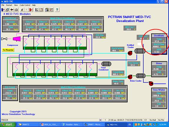
In PCTRAN MED-TVC modeling, we assumed 25% of total turbine steam is extracted as the motive steam at 0.3 Mpa. Going through 4 modules of 14 effects each with top brine temperature at 70°C, a total of 40,000 tons of distillate per day is produced at a gain ratio (GOR) about 13. The electricity, fresh water and process heat can supply a city of 100,000 population.
Transient Simulations of Normal and Accident Operations
1. Power Reduction to 80% and Back to 100%
The reactor power is reduced from 100% to 80% by setting the turbine-driven demand reduction at 10% per minute rate. After stabilization we raise it back to 100%.
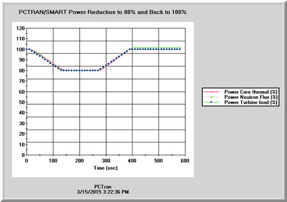
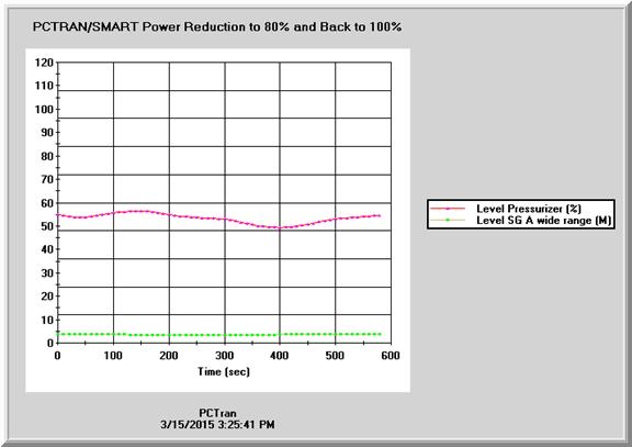
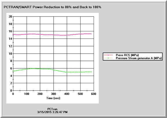
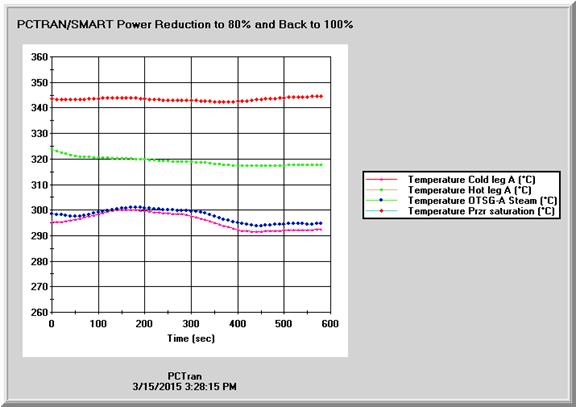
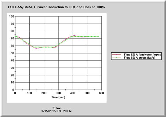
The reactor power, primary and secondary pressures, coolant temperatures, pressurizer and HCSG levels and feedwater and steam flow rates are controlled very stably during the transient course.
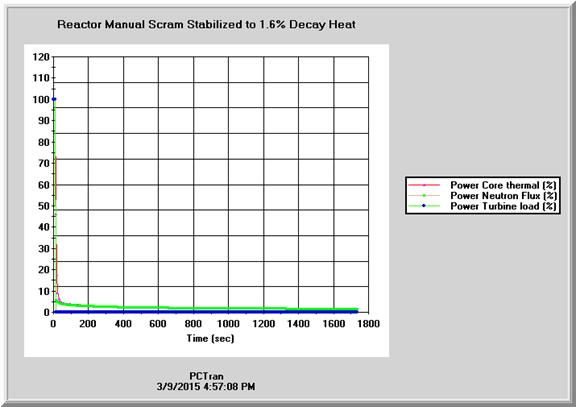
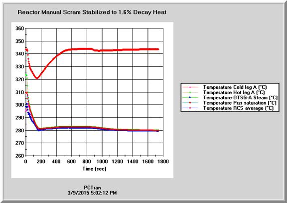
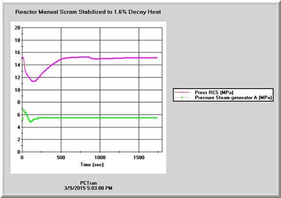
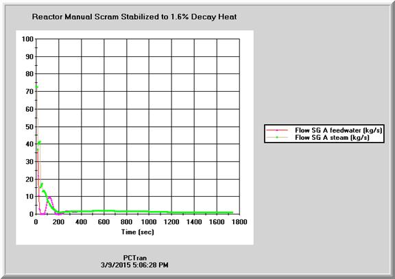
2. Reactor Manual Scram Stabilized to 1.6% Decay Heat
After initialization at 100% power, the reactor is manually scrammed. Without any further operator actions, the reactor is stabilized in hot shutdown condition.

3. Cool-down Using the HCSG’s
Using the previously saved hot shutdown condition, the reactor is cooled down by using the Helical Coil Once-through Steam Generators (HCSG) and steam dump system. We simulate this by clicking on the “Tavg StPt” button in the SG panel and enter the cooldown rate up to 50º C/hr. The steam dump system is adjusted automatically up to the maximum rate. The RCS primary system pressure is passively adjusted by partial pressure of steam and nitrogen gas filled in the self-controlled pressurizer in accordance with variation in pressure and temperature of the primary coolant. We assumed it to maintain 30ºC subcooling in the hot leg. When the RCS pressure is decreasing, the safety injection (SI) must be disabled before reaching its low pressure initiation pressure about 12 MPa. It is completed by using the SI pump’s disable function. Following are the transient plots.


The reactor coolant pumps are then tripped. The MSIV’s are isolated, the pressuriser heaters and CVCS are disabled, too. Next the operators use the normal shutdown cooling system (SDC) to cool down the RCS primary to cold shutdown condition.
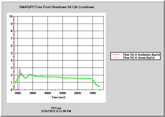
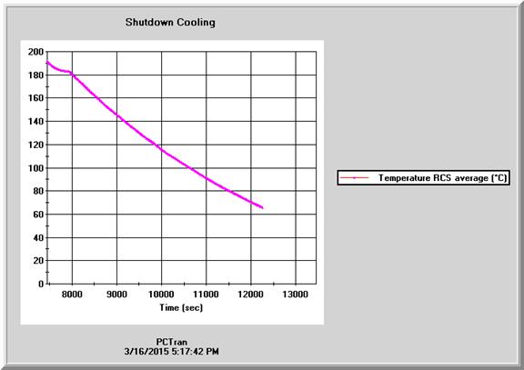
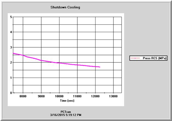
4. Use Normal Shutdown Cooling System to Cool-down to Cold Shutdown
When the RCS condition matches the SDC’s operating condition (about 3 MPa and 300ºC), the RCS is isolated and SDC pumps are turned on. By clicking on the “SDC” button, the pumps start to draw water from the RCS and circulating through the heat exchanger to cool the system till cold shutdown condition (about 50ºC and atmospheric pressure).
So when AC is available to draw vacuum in the condenser and power the SDC, PCTRAN SMART has demonstrated a normal cool-down process.
5. Station Blackout Passive RHR Cooling
For a Fukushima type total loss of offsite and onsite power event, there is no heat sink via the steam dump and SDC systems. The passive RHR system is automatically turned on by opening the drain valve downstream in the steam line submerged in the Emergency Cooling Tank (ECT) of the PRHR system. It is located 10 meters above the SG ‘s outside the containment. Natural circulation prevails to condense the steam from the HCSG’s and returns into the SG feedwater lines. In this run about 500 seconds after reactor shutdown, PRHR is turned on. In the following mimic the steam line valves to the PRHR and the drain line valve are opened in red. All normal AC-powered pumps and valves are disabled as indicated by a red square around the icons.
Transient plots for the first four hours after shutdown using PRHR cooling are shown below:

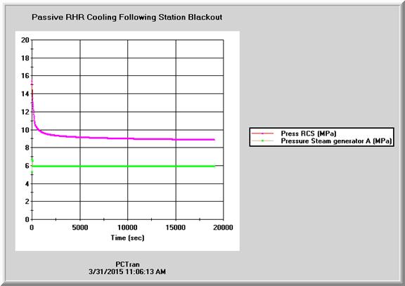
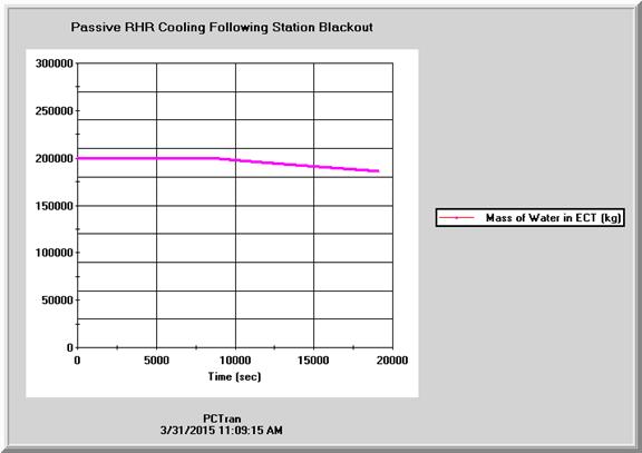
Water in the tank is heated up to boiling in a couple hours. The reactor remains in high pressure but under control. Amount or water in the ECT can maintain the reactor core cooled to 200ºC in 36 hours.
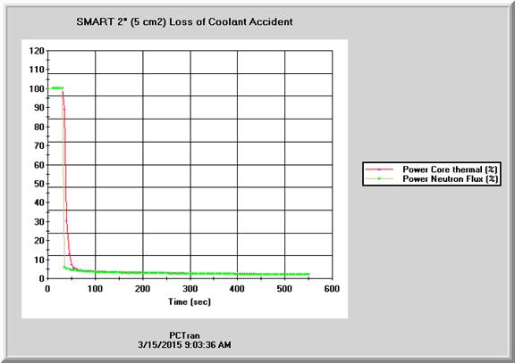
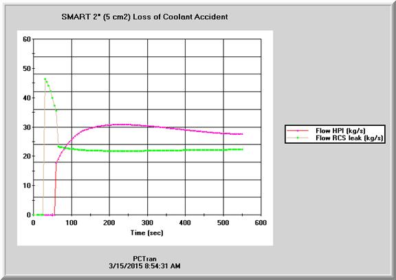
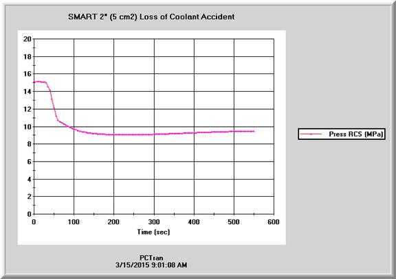
The largest pipes of SMART reactor vessel are limited to 2 inches in diameter. The break area of 5 cm2 is entered in Malfunction 2 for a feedwater line break.
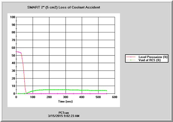
The reactor is quickly shutdown upon the low coolant pressure signal. Turbine trip follows and then AC offsite power is assumed lost. The PRHR is automatically started and the emergency diesel is powered to start the SI system pumps. In the following transient figures the SI flow exceeds the coolant loss within 100 seconds. The pressurizer empties and a void developes in the reactor vessel. However the bubble never drops below the top of the fuel, so the reactor is never in danger as the PRHR is removing the decay heat to the ECT.
7 Severe Accident Mitigation
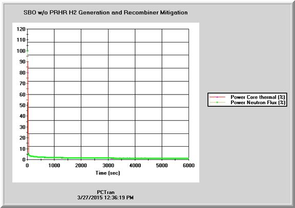
In SMART design philosophy there should be no possibility following any event leading to core-melt and hydrogen production. Still there are 12 passive catalytic recombiners provided for mitigation. In order to test the system’s effectiveness, a SBO without PRHR is hereby tested.
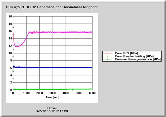
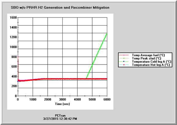
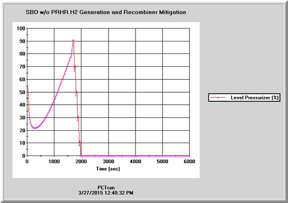
In the following transient plots first the reactor is scrammed so that the heat source is decay heat. Next are the primary, secondary and containment pressures. The RCS pressure drops after reactor trip and the SG’s secondary boiled dry quickly. Owing to loss of heat sink, RCS pressure recovers to cycle around the relief valve set point. When the complete RCS becomes saturated and the pressurizer level approaches “water solid”, liquid or two-phase discharge empties the pressurizer and voids appear in the vessel. When the two-phase level exposes the top of the fuel, the clad temperature heats up to 1000ºC and starts to generate hydrogen. Operators then turn the PAR recombiners on. The number can be increased by clicking on the spinners to its maximum of 12. The hydrogen concentration is seen to drop faster with more activated.
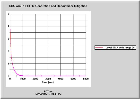
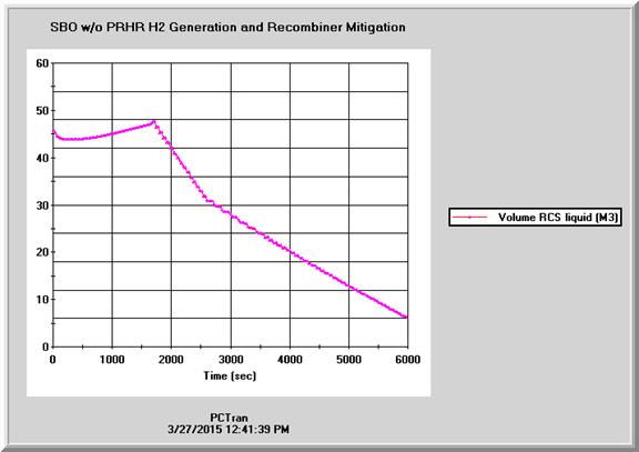
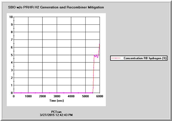
In the final SBO severe accident mimic, the reactor core is exposed with all HCSG’s empty. Hydrogen production rate is balanced by all 12 of the PAR recombiners as indicated in the lower left red circle in the containment panel.
Conclusion
Having conducted entire spectrum of normal and accident cases, PCTRAN/SMART has shown to reproduce all design features with confidence. It is therefore a viable tool for training and education on the small modular reactor. MST has also developed other SMR models such as NuScale 45 MWe passive PWR and Chinese low-pressure Nuclear Heating Reactor (NHR200), etc. Russia has based on her experience in nuclear powered ice breakers and now offer a marine-based barge SMR for electricity and desalination. Having completed a detailed VVER, MST is ready to venture into developing a PC-based simulator for it, too.