 Home | Contact us
PCTRAN NuScale SMR 2017
NuScale power module consists of a small 160 MWt reactor core housed with other primary system components in an integral reactor pressure vessel and surrounded by a steel containment vessel, which is immersed in a large pool of water. Above the core is a shroud, two independent set of helical coil steam generator tubes surrounding the hot leg riser. The HCSG consists of two separate sets of feedwater inlet and steam outlet lines. A set of pressurizer heaters and sprays is located in the upper head of the vessel to provide pressure control.
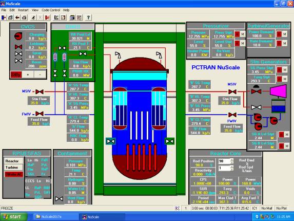
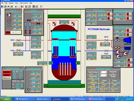
PCTRAN simulator models NuScale design by setting the module in the middle. The chemical and volume control system (CVCC), decay heat removal system (DHS) and containment heat removal system (CHRS) are at upper left. The reactor protection system (RPS) and containment control panels are at lower left. The pressurizer, turbine and steam generators, and reactor core control are at right hand side.
The purpose of this PC-based simulator is not just for the control room operator training, but also for prospective clients in their evaluation of the technology. They learn how the passive-cooled inherent safe SMR works. In a quantitative and dynamic hand-on practice, the reactor performs well in startup, load control, electricity generation and desalination water production. They may also practice any combination of accident scenarios including feed and steam line breaks, SG tube leak, up to the most challenging Fukushima type station blackout up to 30 days – without any possibility of damage to the core or dose release.
Normal Power Reduction, Shutdown and Cooldown by DHRS
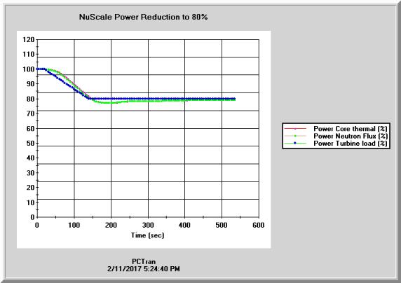
A normal operation starting from 100% power, operators perform a power reduction by clicking on the turbine power demand to 80% with 10%/min rate. The reactor is stabilized at 80%. The pressurizer pressure are controlled be the Chemical and Volume Control System (CVCS). Reactor power is controlled by the rods, and SG pressure and level by the steam dump and feedwater control system as any typical PWR.
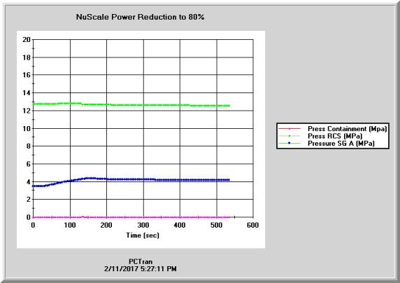
In the following transient figures, not the power ramps down to 80% and stabilized. The RC pressure maintains nearly constant and the HGSG pressure increases slightly. Note the containment is deep sub-atmosphere to provide insulation between the vessel and reactor building pool water.
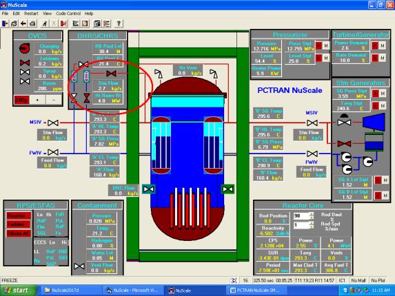
After shutdown if the feedwater or steam dump system is not available, the DHRS is started by opening the steam and condensate return valves of the heat exchanger submerged in the Reactor Building pool. One system is sufficient to remove the decay heat. The figure below shows right after shutdown one train of DHRS is activated and the pool temperature is slowly heating up to boiling.
Decay Heat Removal Using the Containment Pool
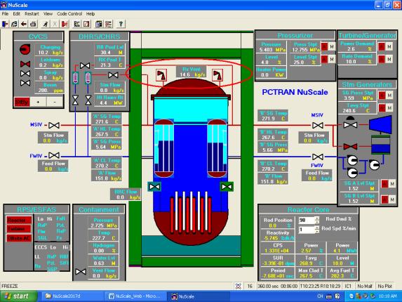
A station blackout is initiated by clicking on the “Offsite power” button in the lower left panel. The reactor scrammed within a few seconds. SG cool-down is not possible since no normal feedwater and vacuum is lost for cooling by the condenser. In the figure below the red oval shows the reactor vent valves are opened to relieve reactor dome steam into the sub-atmospheric containment. Since the steel liner of the containment is submerged in the reactor building water pool, by conduction in the steel wall and natural convection in the pool water, core decay heat slowly heats up the pool water under atmospheric pressure.
The amount of water in the pool (4 million gallons for 12 modules) provides up to 30 day cooling followed by indefinite period of air cooling. Using PCTRAN the simulation speed could accelerate up to 16 times faster than real-time. It is still unbearably slow in training class. We can use previously stored intermediate conditions for restart and demonstrate every typical stage. The tool can also be used by prospective customers who are not nuclear professionals to assess SMR feasibility.
When the containment is pressurized to be in equilibrium with the depressurized reactor vessel, operator opens the reactor recirculation valves (RRV) to return water into the core. The falling core water level then recovers. There is a high margin above the active fuel in all time. In the figure below the two red ovals show containment water refills back into the core.
Small Break Loss of Coolant Accident
A 100 cm2 steam line break inside the containment is initiated. The reactor is soon scrammed on low RC pressure. Assuming loss of offsite power, the RVV’s are opened to speed up reactor vessel depressurization. The containment is soon filled up above the RRV’s elevation so water recirculates back into the reactor core. PCTRAN’s result is in agreement with NuScale’s test and RELAP5 analysis.
Above transient plots closely resemble to NuScale RELAP5 analysis shown below:
Decay Heat Removal 3 to 10 Days
Restart from a previously saved condition of 10 days after scram, the reactor building pool level is at middle of the containment vessel.
Note in the above mimic, in the upper center left DHRS panel, steam and drain valves are open in red. The pool water temperature is boiling at 100 C to atmosphere. The pool water level is half way as the 2nd picture of NuScale Power provided sketch below:
In the above figure the RVV’s are opened so water in the containment is recirculated back into the core and keep it covered indefinitely.
DHR After 30 Days Air Cooling
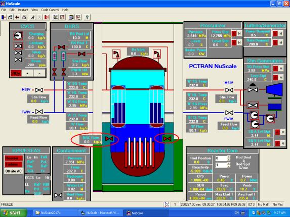
Thirty days after shutdown the reactor building pool is completely boiled dry. Air cooling is sufficient to remove the decay heat. PCTRAN can demonstrate this condition in the following mimic. Note there is no water in the pool. It represents the 3rd stage in NuScale Power’s description.
In the above picture 30 days after shutdown, the containment is cooled by air circulation in the reactor building.