

Home | Contact us
|
|
Home | Contact us |
|
|
PCTRAN HTGR
PC-based Simulator for High Temperature Gas Cooled Reactor
May 2009
A PC-based simulator for High Temperature Gas-Cooled Reactor (HTGR) is successfully developed. It is intended for education and study of all types of gas-cooled reactors. Both prismatic and pebble bed modular designs are included. Using Microsoft Visual Basic language and operates under Windows XP operating system, the input and output are in Access database and operation is by graphic user interface. The platform is convenient for understanding both the reactor core and the power conversion system. A demo download is available.
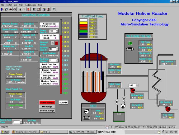
The prototype HTGR generates anywhere from 10 MW for an experimental device up to 600 MW per module for a multi-modular power plant. The reactor outlet temperature is in the order of 800ºC to 1000ºC. The helium pressure is from 3 to 8 MPa. The core helium flow is driven by a circulator and regulated between 30% to100% of rated speed.
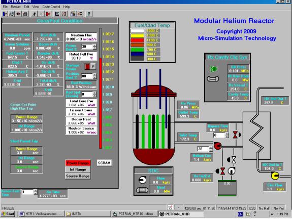
There are graphite reflectors in both the annular and central column regions. The black assemblies in the core represent the reflectors. A neutron source is provided for the initial flux. Operators pull the control rods to reach criticality. Fission energy is transmitted from either the prismatic fuel assemblies or TRISOP balls to the helium coolant. The fuel’s color changes during its temperature rise.
The reactor vessel also becomes very hot. Heat transfer is by a combination of conduction, convection and radiation to the containment air. There is a Reactor Cavity Cooling System (RCCS) that removes the containment heat. By natural convection of the air and use of cooling water at heat exchanger’s secondary side, heat is removed to the atmosphere. After reactor shutdown the Shutdown Cooling System (SCS) is turned on that draws a small amount of the helium gas from the vessel bottom and cooled by a heat exchanger.
In addition to the rod control, the unit power production can be controlled by 1) bypass valve of the circulating helium flow to the power conversion unit, 2) helium temperature control and 3) extraction and addition of helium. To reach a given power level, bypass is the fastest because it directly returns a portion of circulating helium back to the reactor (without going through the power conversion unit). Temperature control is the slowest because the large core fuel and moderator heat capacity. In between the helium inventory control is most commonly used. An extraction valve from the circulating system to a tank is for extraction and another valve with pump is for pumping helium into the system. A proportional plus integral logic is used to control these valves on the helium pressure. They are successfully modeled in the simulator.Since the power conversion system is open to various designs, a simple pressurized-water heat exchanger is used for now in this prototype as heat sink. Super heated steam is generated to drive the turbine/generator. Practical design could use either direct or indirect gas turbines or steam generation. High temperature helium can also be used for hydrogen production. Following is a sample of General Atomic planned gas turbine power conversion system. There are turbine, recuperator, compressors, water heat exchangers and cooling tower in the schematic sketch:
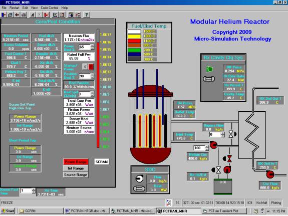
Figure 1 PCTRAN/HTTP plant mimic
All transient variables can be viewed during operation in a separate screen or saved in Access database for documentation.
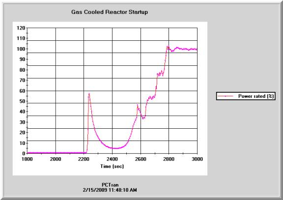
Here a reactor startup is demonstrated. Operators start drawing rods from a cold shutdown condition. A neutron source is present to provide the initial flux. As the total reactivity becomes less negative and approaches criticality (i.e. k-effective = 1), the neutron flux increases with the thermal fission power. A single button is provided to switch from startup “S” mode to power “P” mode. Instead of pulling the rods to a specific position, a power level demand is entered. Rod pulling is controlled automatically via a proportional-plus-integral logic to the desired power level. The fuel and helium coolant are heated up during this process. The variable speed helium circulator controls the core flow rate so that both outlet and inlet temperatures are maintained within designed range. There are helium makeup tank and extraction tank to control the core helium pressure.
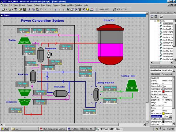
Figure 2. Power Conversion System Mimic (not incorporated into PCTRAN yet)
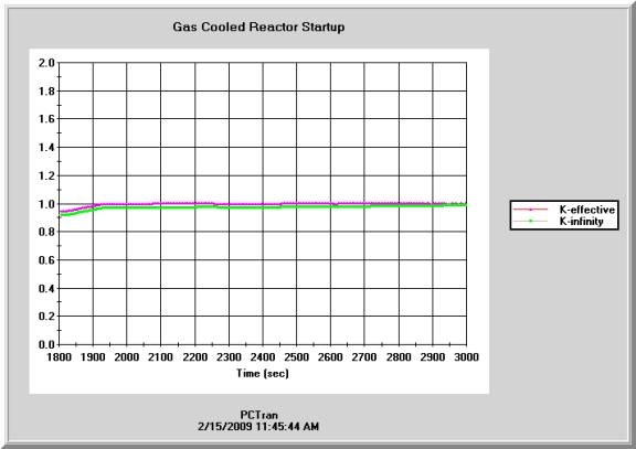
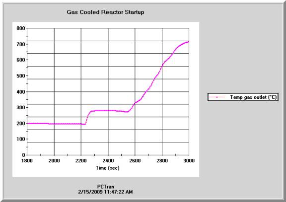
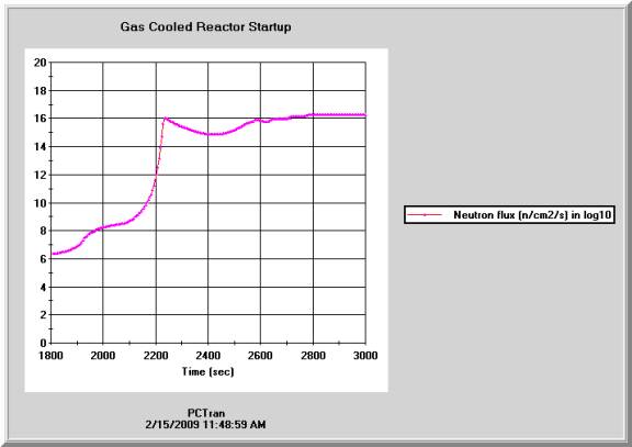
For plant startup, operators start drawing rods from a cold shutdown condition. A neutron source is present to provide the initial flux. As the total reactivity becomes less negative and approaches criticality (i.e. k-effective = 1), the neutron flux increases with the thermal fission power. Following are transient plots of reactivities, helium gas temperature, core power, neutron flux, and helium flow from cold shutdown to full power. Note there is a power or flux peak prior to power ascension. That is because the operator pulled the rods too fast before switching to the “Power” mode. Rapid fuel temperature increase has caused natural Doppler feedback to suppress power ascension. By switching to automatic power control it turned into more stable till reaching the full power. The neutron flux in log –10 scale at full power is about 2x10¹⁶ n/cm2/sec
The second case is benchmark of GA’s simulator for power reduction from 100% to 65%.
The reference is GA-A21784 published in 1994.
We ran PCTRAN HTTR starting from 100% power and staggered reduce the power by 1% for every 2 minutes. PCTRAN results are shown below:
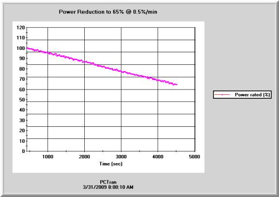
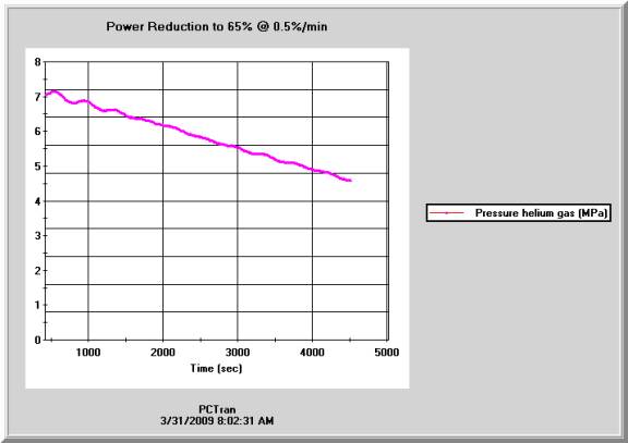
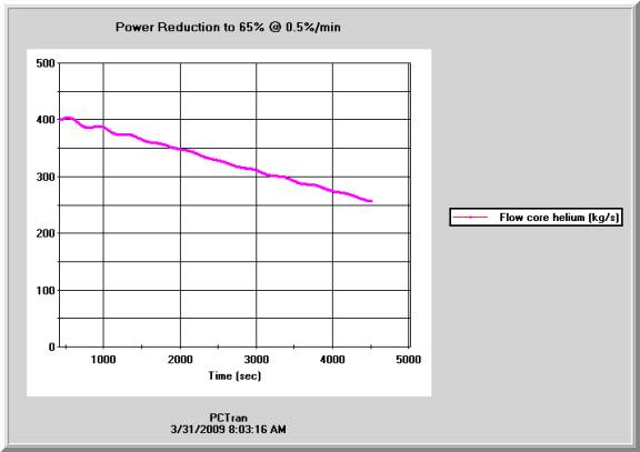
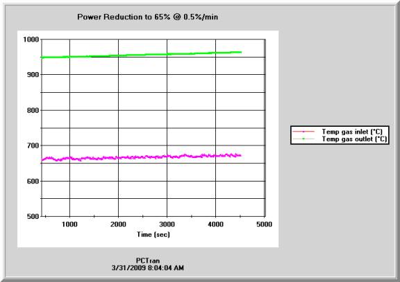
Table 1 Comparison between GA and PCTRAN simulations:
Variable |
GA simulator |
PCTRAN |
Comment |
Rx Power |
Down to 65% in 60 minutes |
Down to 65% in 60 minutes |
OK |
Outlet temperature |
Constant |
Up slightly |
Possible difference in power control logic |
Inlet temperature |
Down slightly then up |
Up slightly |
Possible difference in power control logic |
Helium flow |
Down significantly |
Down significantly |
OK |
Helium pressure |
Down |
Down |
OK |
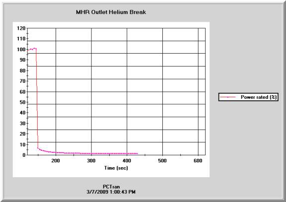
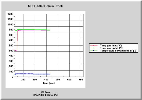
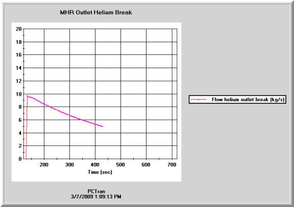
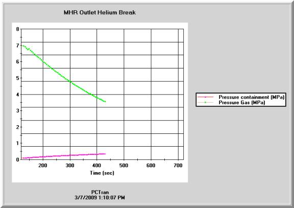
To test the reactor under accident conditions, a helium outlet break of 10-kg/sec flow into the containment building is initiated. The reactor is soon tripped on detection of reduced helium pressure and increased containment pressure and temperature. The Reactor Cavity Cooling System (RCCS) is operating to remove the additional heat input to the containment.
The following paper was selected for PCTRAN verification:
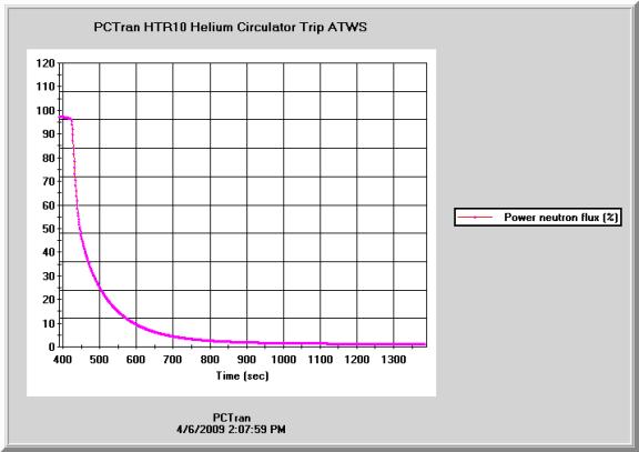
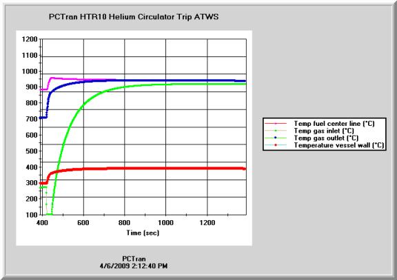
The PCTRAN HTR-10 model is first brought to critical and maintained near 100% power. The key operating variables are:
Toutlet = 703.7 C
Tinlet = 252.1 C
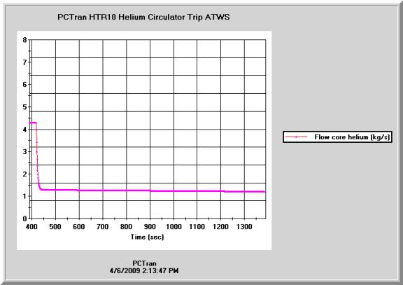
He Circulation flow = 4.28 kg/sec
Core power = 10 MW
He pressure = 2.96 MPa
Then the helium circulator is tripped without incurring a reactor scram. Following are the key transient plots. The reactor went into subcritical with only its decay heat being removed by the shutdown cooling system. The gas outlet temperature increased from 700ºC to about 960ºC and then decreased.
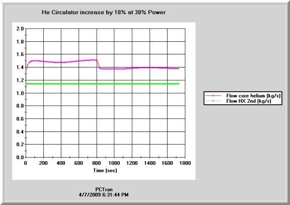
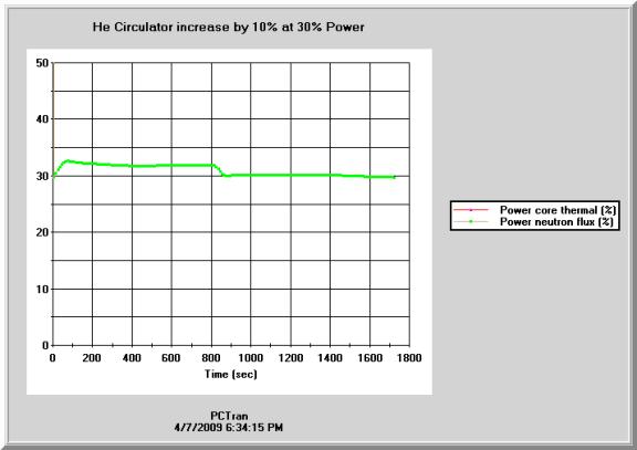
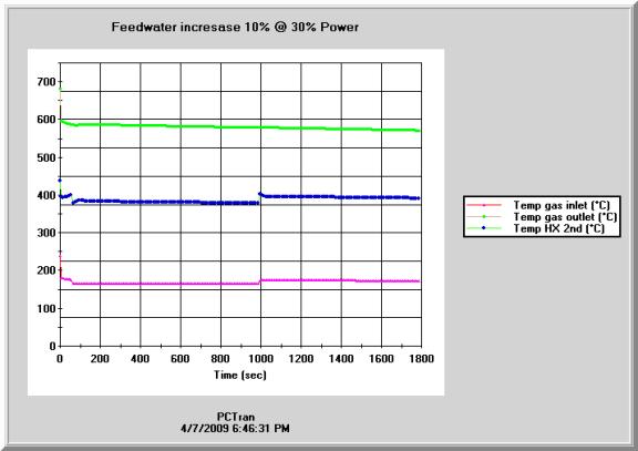
A steady state at 30% power is created for benchmark of three operational transients:
Benchmark |
INET |
PCTRAN |
Power |
30% |
30.18% |
Thot |
593C |
599.3 C |
Tcold |
200C |
172.3 C |
He Flow |
1.43 kg/s |
1.4 kg/s |
Feedwater flow |
1.1 kg/s |
1.1 kg/s |
He pressure |
? |
0.86 MPa |
Steam Temperature |
330 C |
397 C |
1. Rod Withdrawal from 30% Power
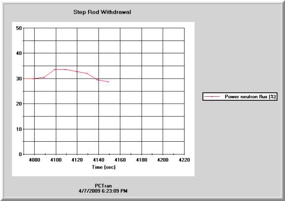
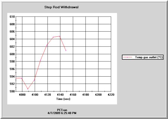
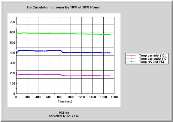
2. Varying Helium Circulation Rate
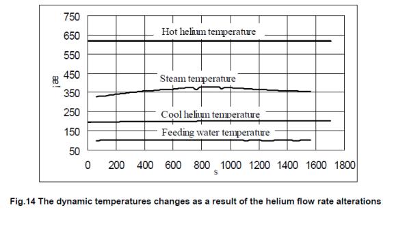
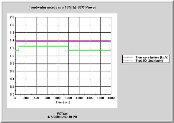
3. Feedwater Alternations
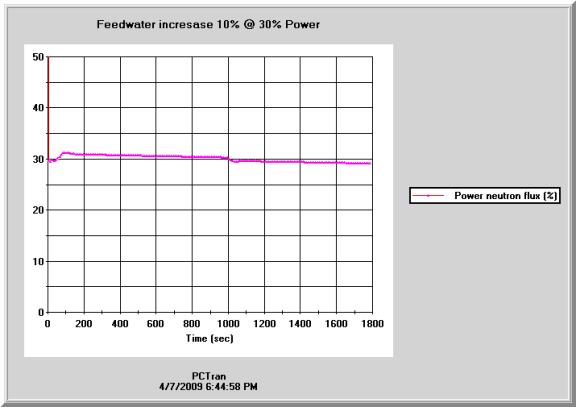
Micro-Simulation Technology has experience in delivery to Japan Atomic Energy Research Institute (currently JAEA) a PC-DOS simulator for its 30-MW High Temperature Test Reactor (HTTR) in Oarai back in 1998. All the transient and accident analysis cases are well reproduced in that simulator. As PC technology has advanced into Windows with powerful graphic-user-interface (GUI), the new platform is ideal for future development. Any sophisticated algorithm unique for gas-cooled reactor can be in principle “transplanted” into this platform.
Even in its early development stage, PCTRAN/HTGR prototype has already shown HTGR’s unique advantage in passive or inherently safe characteristic. HTGR is known for resilience to all plausible accidents owing to inherent safe characteristics. The transient time is typically in the order of days rather than minutes or hours for light water reactors. The fast run function of PCTRAN up to 64 times faster than real-time is valuable in training and analysis. We plan to conduct a full line of postulated transient and accident cases. It includes both pressurized and depressurized loss of forced circulation (P-LOFC and D-LOFC) and anticipated transient without scram (ATWA). The published literature based on Oak Ridge National Laboratory’s GRSAC code will be used for benchmark.
In light of construction of the first Generation IV plant in China, the PC-based tool can even be used for demonstration of the gas-cooled reactor’s unique features and advantage in efficiency and reliability. Owing to its simplistic yet attractive graphic interface, the audience could be extended to non-technical management, financial backers, government officials or general public.